OC Panel Kit
In keeping with the Extreme moniker of the board, ASUS bundled in the newest version of their hand-held monitoring device with the Rampage V Extreme board – dubbed the OC Panel. The OC Panel device serves dual purpose – monitoring board voltages, temperatures, and fan speeds, as well as on-the-fly overclocking of board voltages and bus speeds.
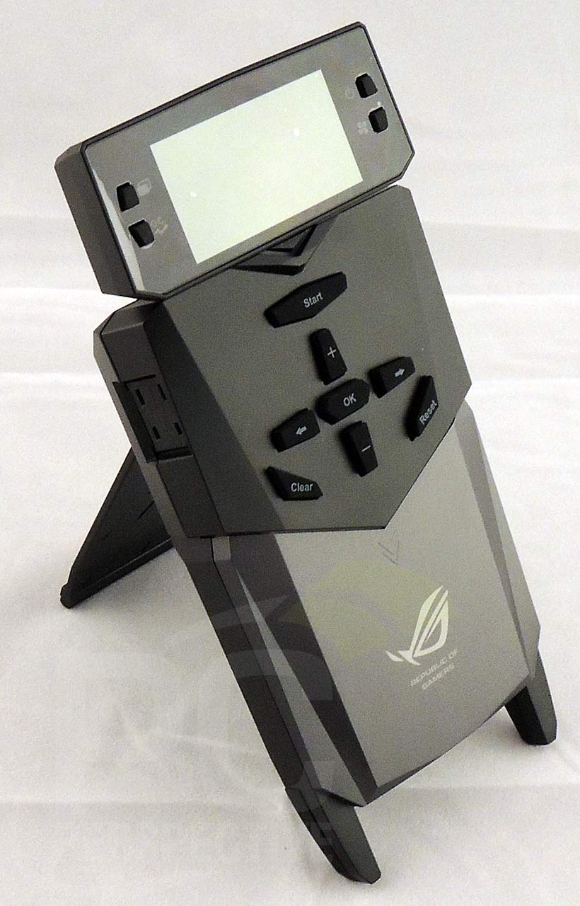
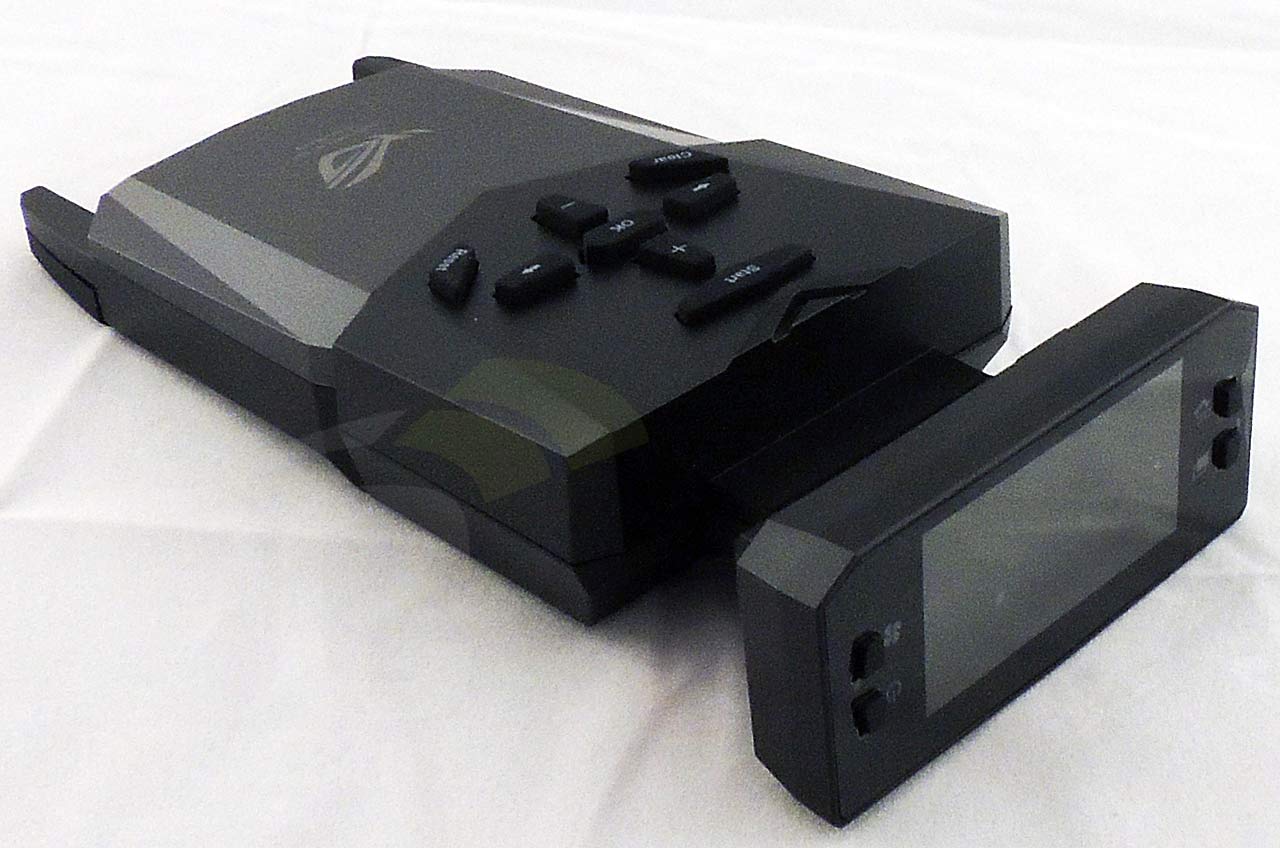
The OC Panel has two modes of operation – Normal mode and Extreme mode. In Normal mode, the panel lays flat in a 5.25" docking enclosure with the screen oriented perpendicular to its body so that is faces out in the dock. In Extreme mode, the panel can be used as a hand-held device or standing upright via its kick-stand. In this mode, the screen is parallel to the OC Panel body.
The OC Panel device has a 2.6" LCM display with mode switch and CPU Level Up buttons to the left of the display, and system power and fan speed control buttons to the right of the display. On the body of the device are control buttons for interacting with the device menus and settings, as well as Clear and Reset buttons.
The kit includes an OC Panel cable used to connect the OC Panel device to the motherboard itself using the headers labeled ROG_EXT on the Rampage V Extreme. ASUS went the extra mile with the OC Panel cable by sleeving the cable wires with dense weave nylon-style sleeving. Note that using the OC Panel cable takes up one of the integrated USB 2.0 headers. The cable plugs directly into the bottom of the OC Panel unit. The unite is powered via the SATA power port by connecting a SATA power connector from the PSU to this port device.
The OC Panel's 5.25" external enclosure is a single bay enclosure made of steel with a plastic face plate. The face plate is embossed with the ROG logo. Also included are 6 screws for mounting the OC Panel into the enclosure and for mounting the enclosure in your case bay. Notice how the bottom of the enclosure has a cut-out section to compensate for the buttons on the device's body.
In Normal mode, the OC Panel device mounts to the included 5.25" drive enclosure with the display face flush with the enclosure front panel. The device mounts to the enclosure via screws through the top of the enclosure that interface with embedded threaded holes on the device's backside.
In Extreme mode, the lower front panel of the OC Panel device can be removed to expose additional headers, measurement points, and direct solder points that can be used for control and informational purposes. The front panel slides down and lifts off the device as shown.
In the upper left corner of the device PCB are the VGA Hotwire headers (6 total headers colored white, red, or black), two 4-pin fan headers, and Probelt voltage measurement points. The VGA Hotwire headers are used for connecting to wires coming from your system video cards to control onboard settings and voltages. The Probelt voltage measurement points allow for direct system voltage measure using a multi-meter.
In the upper right corner of the OC Panel's PCB are two additional 4-pin fan headers, SlowMode and PauseMode switches, and an ASUS internal debug header. When enabled, the PauseMode forces the system to halt at its current state and illuminates an LED connected to the PauseMode header. The SlowMode switch functions the same as the SlowMode switch on the board, forcing an automate system slowdown, slowing the system boot process and CPU frequency, to help prevent system crashing at extreme cooling speeds.
On the upper left side of the device are the Subzero Sense ports. These ports are used to connect a K-type thermocouple probe to get temperature readouts for motherboard devices while using LN2 cooling. Temperature readings from the port are accurate to -193 degrees Celsius.
When the OC Panel device is powered and connected to the Rampage V Extreme board via its connection cable, it provides CPU temperature, base clock speed, CPU fan header RPM speed, and CPU clock ratio by default on its display. Values are display regardless of the board's power state. The displayed values and device functionality can be customized using the control buttons to the right and left of the device's main display.


You appear to have “Courtesy
You appear to have “Courtesy of Gigabyte” dotted around on this article; perhaps you mean “Courtesy of Asus”
You know its Morry that has
You know its Morry that has written this right? We all love him and his work, but he is quite like that grandparent we all have that sometimes puts their shoe in the oven and the milk in the washer.
Thanks for the heads up, its
Thanks for the heads up, its fixed now…
Morry! You magnificent
Morry! You magnificent bastard, I read your article! ~ Derivative quote taken from “Patton” starring Geo. C Scott. 😉
Looks like a good board.
Looks like a good board. Especially now that EK posted a picture of a full coverage monoblock for the Rampage V. Might look into it for an upgrade from an X79 Sabertooth.
Anyone by any chance have an idea why the 2nd card in a crossfire setup would stop being detected in windows after installing Gskill 3333MHz ram?
it *might* be a PCIe voltage
it *might* be a PCIe voltage issue. Try bumping up your chipset related voltages a bit and see if that helps. What speed are you attempting to run the memory at? Could also be that that board cannot maintain stability at spec'd memory speeds with the new DIMMs
It was a client’s PC so I
It was a client’s PC so I don’t have it available anymore. The ram in question had an XMP profile of 3333MHz 1.35V CL16-16-16-36. Wouldn’t always boot at 3333MHz. 3200MHz would work so it was set to that. But I hadn’t thought to check the PCI-E voltage. If I come across the board again I’ll definitely look into that.
The guy was dead set on returning the PC anyways and brought it to me to see if I could get it going. I think the board was just set on making a fool of me.
Better that board than any of
Better that board than any of us! 🙂
Weird, you list “weakness” as
Weird, you list “weakness” as lacking a clear CMOS jumper, but it has a clear CMOS button on the back panel. See your own photo:
https://pcper.com/image/view/51285?return=node%2F62100
Lower left corner just above the ROG connect/USB BIOS Flashback button. It is labeled CLR CMOS
clear CMOS button and clear
clear CMOS button and clear CMOS jumper are different. Jumper can be used to clear all BIOS settings in conjuction with removing the CMOS battery reliably. CMOS button is not as reliable at doing this in practice. The jumper just gives a bit more control over the operation…
I have this board and the
I have this board and the clear CMOS button does exactly as the clear CMOS jumper does on all the other boards I own. It clears the CMOS and resets to default values.
A jumper is nothing more than two pins that when jumpered shorts a circuit, this is what clears the CMOS, it shorts the power to ground.
If you like you can put a DVM on it and test it yourself. They are indeed on in the same.
Noctua NH-D15 cooler seems to
Noctua NH-D15 cooler seems to be very close to the graphics card PCB. What non-conductive material would you use inbetween? Or, in your experience, does it even matter?
If you’re concerned when
If you're concerned when using a cooler like that, you could use one of the following (most of which I have used in my many liquid cooled and force-refrigeration-cooled systems):
– duct-tape
– neoprene pad (thin with adhesive on one side)
– conformal coating -> have to be careful with this, not to get any on conductive surfaces as it will insulate them very well
– backplate for the video card
Thank you so much for the
Thank you so much for the reply
I’ll definitely go with the Neoprene pad and GPU backplate solutions
I always wanted a 140mm kinda Noctua CPU cooler because I simply don’t trust even the 1 in a million chance that there’d be a leakage from CPU water cooling, and that that would be my CPU water cooler purchase
Will be this mobo compatible
Will be this mobo compatible with the next 2016-2017 HMC as replacement for DDR memories ? THKS
unknown, but unlikely based
unknown, but unlikely based on previous Intel release cycles…
I own this mobo an its been
I own this mobo an its been nothing but a nightmare for me. It resets on its own. Locks up. BSOD I have changed power supplies done everything I can think of best advise stay away.
please dont tell ppl to stay
please dont tell ppl to stay away from a board that i have and totally love, you just had a bad board which can happen with any board out there, so no dont stay away from thus board as a novice ocer this board is a beauty.