
Motherboard Layout
Motherboard Layout

The Prime Z270-A features the black and white branding common to ASUS' channel product line with the rear panel cover and chipset featuring the brand logos. The VRM heat sinks are brushed aluminum, meshing well with the white accents on the board's black PCB. The board's aesthetic comes together well, giving the board a high-tech and futuristic type look. The board's layout is spacious with more than adequate room provided between all components for easy user access.

ASUS designed the Prime Z270-A with a total of 10-digital power phases, which provide more than enough power for the most punishing overclocking. ASUS cools the CPU VRM circuitry with two large heat sinks, one above and one to the right of the CPU socket. The socket itself is clear of obstructions, making for an easy CPU cooler mount.


The board is designed with a total of two PCIe x4 M.2 slots, one to the left of the CPU socket and below the primary PCIe x1 slot, and the other underneath the fourth PCIe x1 slot. The M.2 slot by the CPU supports M.2 cards up to 80mm in length, while the other supports cards up to 110mm in length.

The board supports up to four DIMM slots with Dual Channel memory mode active with modules in slots 1 / 3 (black slots) or 2 / 4 (grey slots).

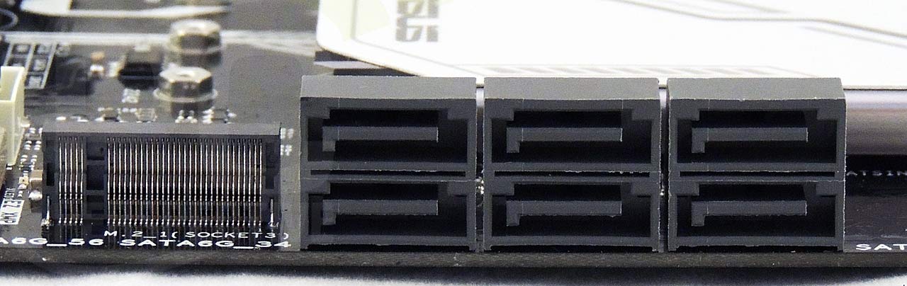
The Intel Z270 chipset is covered by a low profile brushed aluminum heat sink with a white plastic overlay featuring the ASUS corporate logo. In addition to the two PCIe x4 M.2 slots, the board was designed with six SATA III ports in a block just below the chipset heat sink.

The board contains a total of seven PCIe slots – three PCIe x16 slots and four PCIe x1 slots. The PCIe x16 slots can be used in x16, x8 / x8, or x8 / x8 / x4 mode.

With this board, ASUS integrated support for connecting an RGB LED strip to the board using the RGB 12V header located to the along the outside mid-point of the tertiary PCIe x16 slot. Connecting an RGB LED strip to the RGB 12V header synchronizes the LED strip color and activity with that of the motherboard's integrated LEDs in the audio PCB separator line. In the screencap, an RGB cable is connected to the RGB 12V header.

New to the Z270 board line, ASUS integrates mount points for custom designed 3D printed panels and accessories. The mount points are along the upper edge of the board, just below the audio PCB illuminated divider line.

The Prime Z270-A board contains the following ports integrated into its rear panel: a PS/2 hybrid keyboard / mouse port, four USB 3.0 ports (blue), two USB 3.1 10Gbps ports – one Type A (teal) and one Type C (black), one GigE RJ-45 port – an Intel I219-V NIC, an HDMI output port, a DisplayPort video output port, a DVI-D video output port, an S/PDIF digital audio output, and five analogue audio outputs.


Hey no SATA express… Said
Hey no SATA express… Said no one ever.
Great review!
I would like to
Great review!
I would like to know if there is enough room for large CPU Air coolers like Be Quiet! Dark Rock PRO 3?
see https://www.techpowerup.com/reviews/beQuiet/Dark_Rock_Pro3/5.html
Thanks for answer
Pavsko
Does Prime A has the same
Does Prime A has the same power phase as Prime AR?
For the Cons – “Cmos battery
For the Cons – “Cmos battery replacement”!!!. does it mean we cant change the cmos battery once it dies???. Which ram I need to get – 1.35v or 1.2 v? Thanks in advance.